UPS can distribute the power source to the critical load of the data center in case of emergency. In the power supply guarantee system for every data center, UPS has played an indispensable role. So, what does redundancy in the data center mean? What are the common redundancy methods? Those will be summarized in the following aspects.
I. Data Center Capacity "N"
1. Redundancy in the data center
For a long time, many design engineers have tried to create perfect UPS solutions to support critical loads. Design engineers and manufacturers have many names for redundant systems, such as parallel redundancy, isolation redundancy, distributed redundancy, thermal connection, thermal synchronization, multiple parallel buses, system plus system, capture system and isolated parallel connection, etc. The problem with these terms is that they have different meanings to different people and can be interpreted in different ways, but the names of these designs often do not necessarily indicate their position within the scope of availability.
There are currently four most commonly used UPS redundancy methods on the market, including:
1) Isolation and redundancy;
2) Parallel redundancy;
3) Distributed redundancy;
4) Dual system redundancy.
Below, we will introduce these four redundant systems one by one.

2. Definition of capacity "N"
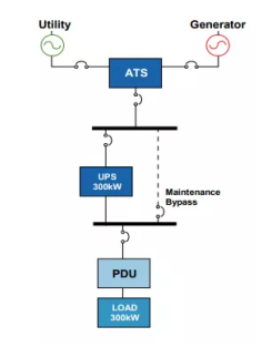
The capacity “N” system is composed of a single UPS module or a group of modules whose capacity matches the critical load in parallel. A single system is currently the most common configuration in the UPS industry.
For a computer room with a design capacity of 400kw, whether it is equipped with a 400kw UPS or two 200kw UPSs connected in parallel on a common bus, it is of N configuration. The N configuration can be seen as the minimum requirement to provide protection for critical loads. Most of the “N” system configuration, especially the system below 100kw, are installed in the building, and do not particularly care about the configuration of the overall electrical system in the building.
II. Four Common Redundancy Methods
1. Isolation and redundancy
Isolation redundancy refers to an “N+1” system, however, it is very different from a parallel redundant configuration (also known as “N+1”). The isolation and redundancy design concept does not require parallel buses, nor does it require modules to have the same capacity, or even from the same manufacturer. In this configuration, there is a main UPS module, which usually supplies power to the load. The “isolated” or “secondary” UPS supplies power to the static bypass of the main UPS module. This configuration requires a separate static bypass input for the main UPS module. This is a way to achieve redundancy for previous non-redundant configurations without the need to completely replace the existing UPS.
In a normal operation scenario, the main UPS module carries all critical loads, and the isolation module is completely unloaded. When the load of the main module is transferred to the static bypass, the isolation module will immediately accept the full load of the main module. In this way, the isolation module must be carefully selected to ensure that it can bear the load so quickly. If it cannot be carried quickly, it may itself transfer to a static bypass, thereby undermining the additional protection provided by this configuration. Generally speaking, the reliability gains brought by this configuration are often offset by the complexity of the switchgear and related controls.
Advantages of isolation redundancy:
a. Flexible product selection, products can be mixed with any brand or model;
b. Provide UPS fault tolerance;
c. No synchronization required;
d. For dual UPS system redundancy, the cost-effectiveness is relatively high.
Disadvantages of isolation redundancy:
a. Rely on the correct operation of the static bypass of the main module to receive power from the standby module;
b. The static bypass of the two UPS modules must work normally to provide current exceeding the capacity of the inverter;
c. Since the secondary UPS load is 0%, the operating cost is high, and it needs to be pumped to maintain operation;

2. Parallel redundancy
Parallel redundancy (also known as “N+1” configuration) allows a single UPS module to fail without the need to transfer critical loads to utility power sources. This configuration is to connect multiple UPS modules of the same size in parallel to a common output bus. If the backup power is at least equal to the capacity of one system module, the system is N+1 redundancy; if the backup power is equal to two system modules, the system is N+2 redundancy. The parallel redundant system requires that the capacity and model of the UPS modules are the same. The output of the module is synchronized through an external parallel board, or in some cases, this function is embedded in the UPS module itself. The UPS modules with parallel redundancy design share the critical load equally under normal operating conditions. When one of the modules is removed from the parallel bus (or if it is removed due to an internal fault), the remaining UPS modules need to immediately accept the load of the failed UPS module. This capability allows any module to be removed from the bus and repaired without the need to connect critical loads directly to the grid.
Advantages of parallel redundant design:
a. Compared with isolation redundancy, the probability of failure is lower, because there are fewer circuit breakers and the module is always online;
b. Can be expanded when the power demand increases. Multiple units can be configured in the same installation;
c. The hardware layout concept is simple and cost-effective.
Disadvantages of parallel redundant design:
a. The two modules must be the same design, same manufacturer, same rating, same technology and configuration;
b. There is still a single point of failure in the upstream and downstream of the UPS system;
c. Lower operating efficiency – single device has a utilization rate < 100%;
d. Single load bus for each system, single point of failure.

3. Distributed Redundancy
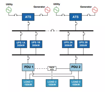
Distributed redundancy configurations, also known as triple redundancy, are commonly used in today’s large data center market, especially in financial institutions. The basis of this design uses three or more UPS modules with independent input and output feeders. The independent output bus is connected to the critical load through multiple PDUs. From the grid entrance to the UPS, the distributed redundancy design and the dual system design are very similar, both provide concurrent maintenance and minimize single points of failure. The main difference lies in the number of UPS modules required to provide redundant power paths for critical loads. As the load demand “N” increases, the number of UPS modules saved also increases. In general, distributed redundant systems are often used for large multi-megawatt installations that require parallel maintenance and limited space.
Advantages of distributed redundancy design:
a. Compared with the 2(N+1) design, there are fewer UPS modules, which saves costs;
b. From the perspective of any given two-wire load, two separate power paths provide redundancy from the service entrance;
c. UPS modules, switch cabinets and other power distribution equipment can be maintained without transferring the load to bypass mode.

Disadvantages of distributed redundant design:
a. Compared with the previous configuration, the cost has become very high due to the widespread use of switches;
b. In a large installation with many UPS modules, many static transfer switches and PDUs, it is difficult to maintain system load balance;
c. The system has many operating modes and switches, which make manual operation and maintenance difficult;
c. Because the UPS is operating normally below full load, there is a problem of low efficiency.
4. Dual System Redundancy
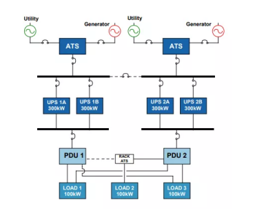
“System + System”, “Isolated Parallel Connection”, “Multiple Parallel Bus”, “Double End”, “2(N+1)”, “2N+2”, “[(N+1) + (N+1) ]” and “2N” are both names for this structural variant. With this design, it is now possible to create a stand-alone UPS system, which may never require load transfer to the grid. These systems can be designed to eliminate all possible single points of failure. However, the more single points of failure eliminated, the higher the cost of implementing this design.
Most large-scale dual-system installation UPSs are located in separate, specially designed buildings. It is not uncommon for infrastructure support spaces (UPS, batteries, cooling, generators, utilities, and power distribution rooms) to be the same size or larger than data center equipment space. This is the most reliable and expensive design in the industry. It can be very simple or very complex, depending on the vision of the engineer and the requirements of the owner.
Advantages of dual system redundancy design:
a. Two separate power paths allow no single point of failure, and the fault tolerance rate is high;
b. Configuration provides complete redundancy from service entrance to critical load;
c. In the 2(N+1) design, UPS redundancy still exists, even during concurrent maintenance
d. It is easier to maintain the uniform load of the system and know which system supplies power to which load.

Disadvantages of dual-system redundant design:
a. A large number of redundant components makes the dual system the most costly solution;
b. UPS has been in a low-efficiency operating state for a long time;
c. The power distribution building needs a new design to adapt to the UPS system.
Read more related topics here: https://usdc.vn/blog/


